Advanced configuration
LCDs are a convenient way to display multiple numeric values on one output device. The following steps demonstrate how to use a display to show multiple radio values from Microsoft Flight Simulator 2020 and Microsoft Flight Simulator 2024.
Note
This guide assumes prior knowledge of creating output configurations. To learn how to create a basic radio output configuration, see the 7-segment display output configuration guide.
Add output configurations for each value
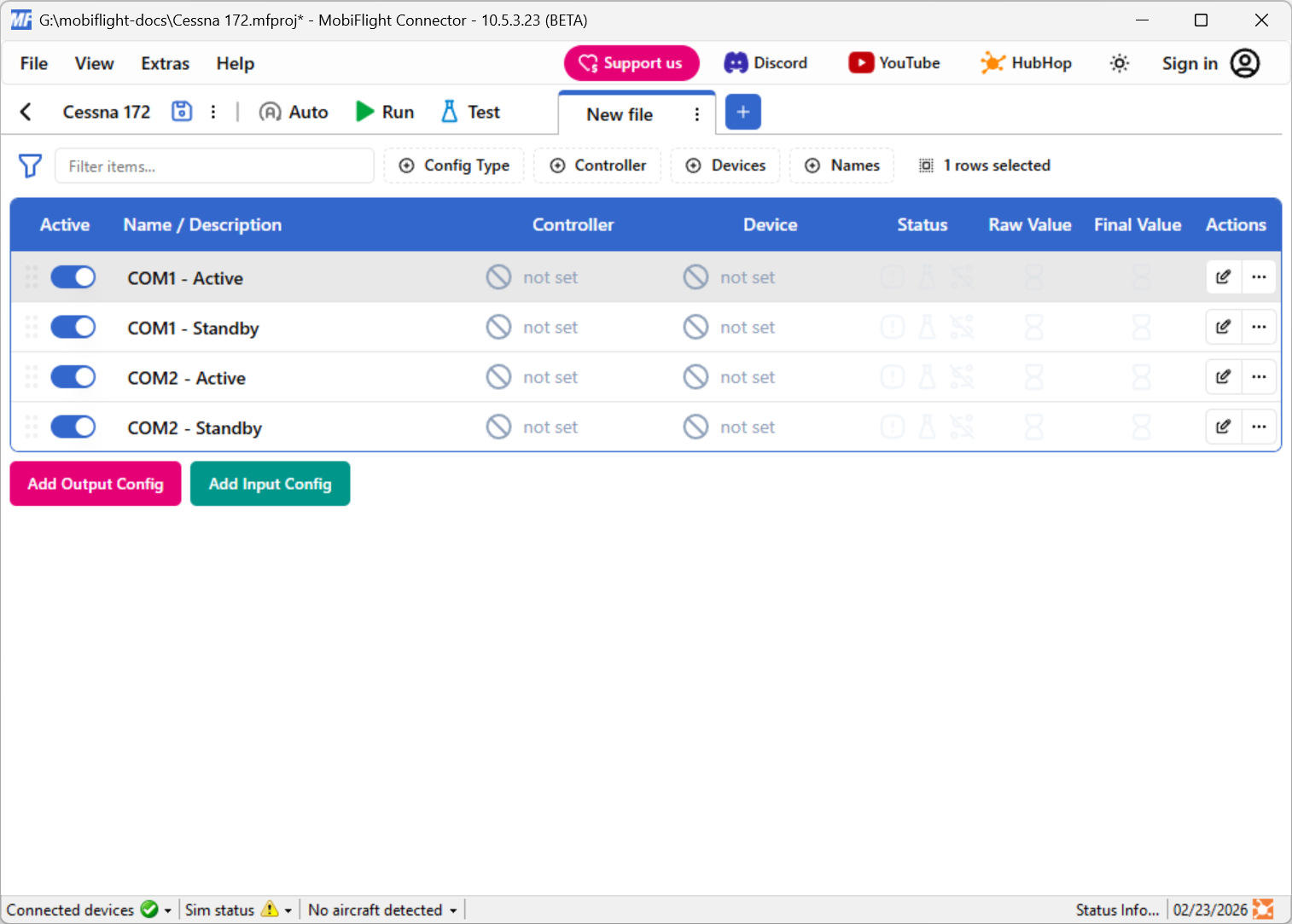
Use the output tab to create one output configuration for each value to display on the LCD. For example, create rows for the COM1 and COM2 active and standby frequencies.
Each output should have the Sim Variable tab configured for the desired value. The Display tab should be left blank.
Create an LCD output configuration
Click the Add Output Config button to add a fifth output, which will display the values on the LCD.
Add config references to an LCD output configuration
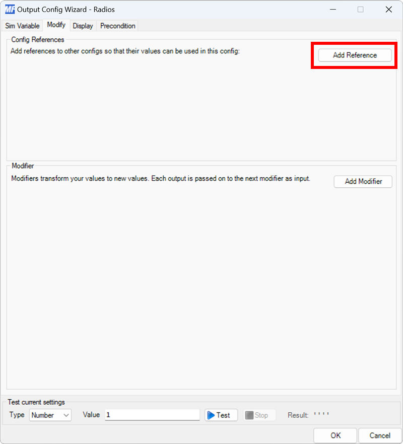
Add a new output configuration for the LCD, but do not select a variable on the Sim Variable tab. Instead, click the Add Reference button on the Modify tab.
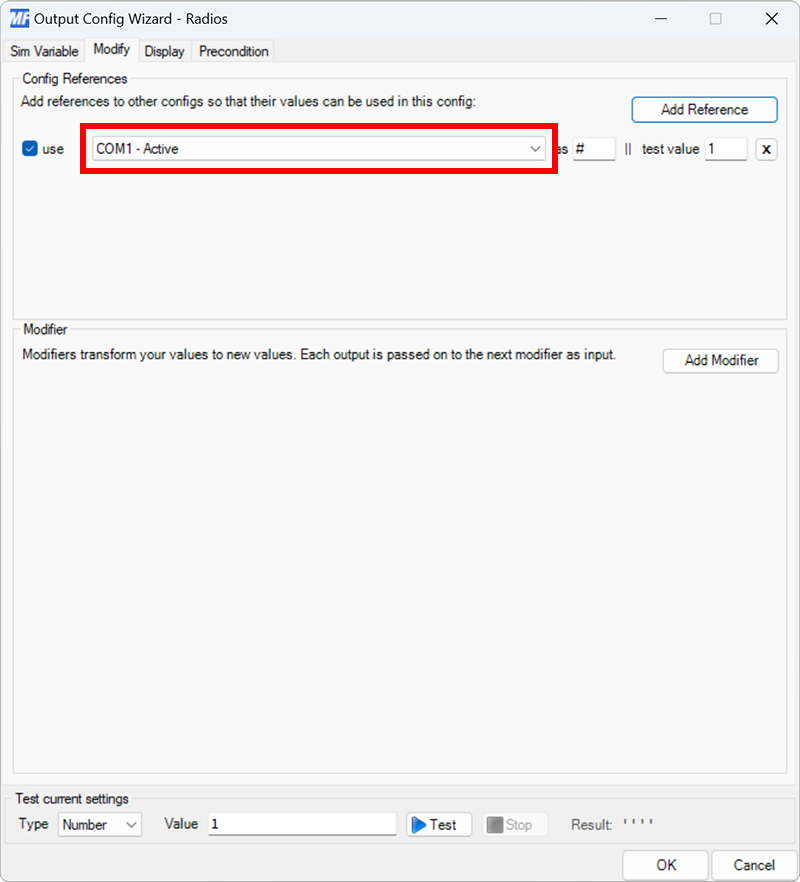
A new reference to an existing output configuration will be added. If the selected reference is not one of the radio values configured in the previous step use the dropdown to select the correct output.
Add the remaining references
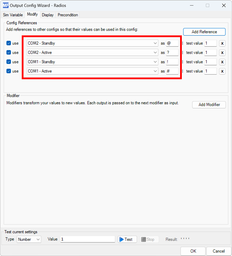
Repeat the previous step three more times to add config references to the remaining three radio values.
Tip
Write down the characters associated with each config reference for use in later steps.
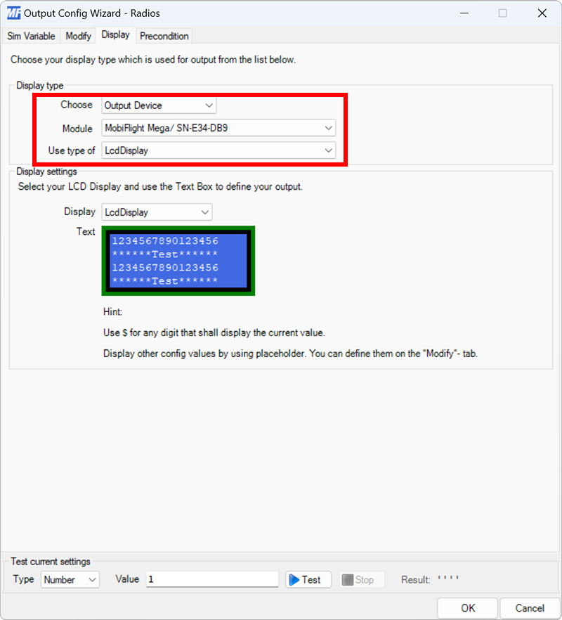
Select the board and device type for the output
On the Display tab, use the Module and Use type of dropdowns to select your connected board and the LcdDisplay device type.
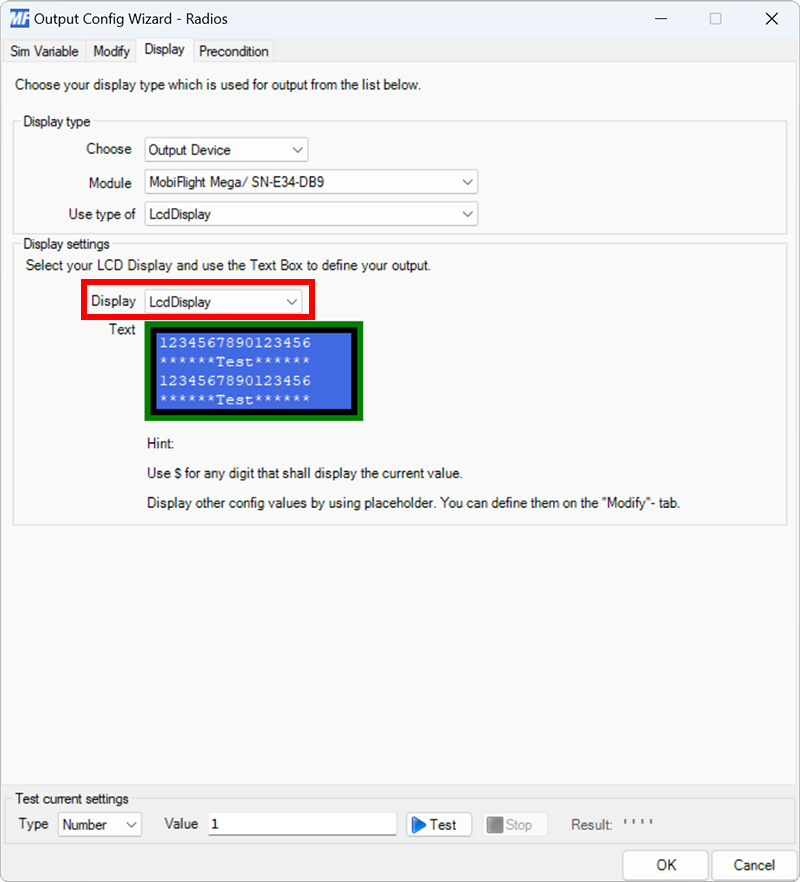
Select the device
Use the Display dropdown to select the specific display to use.
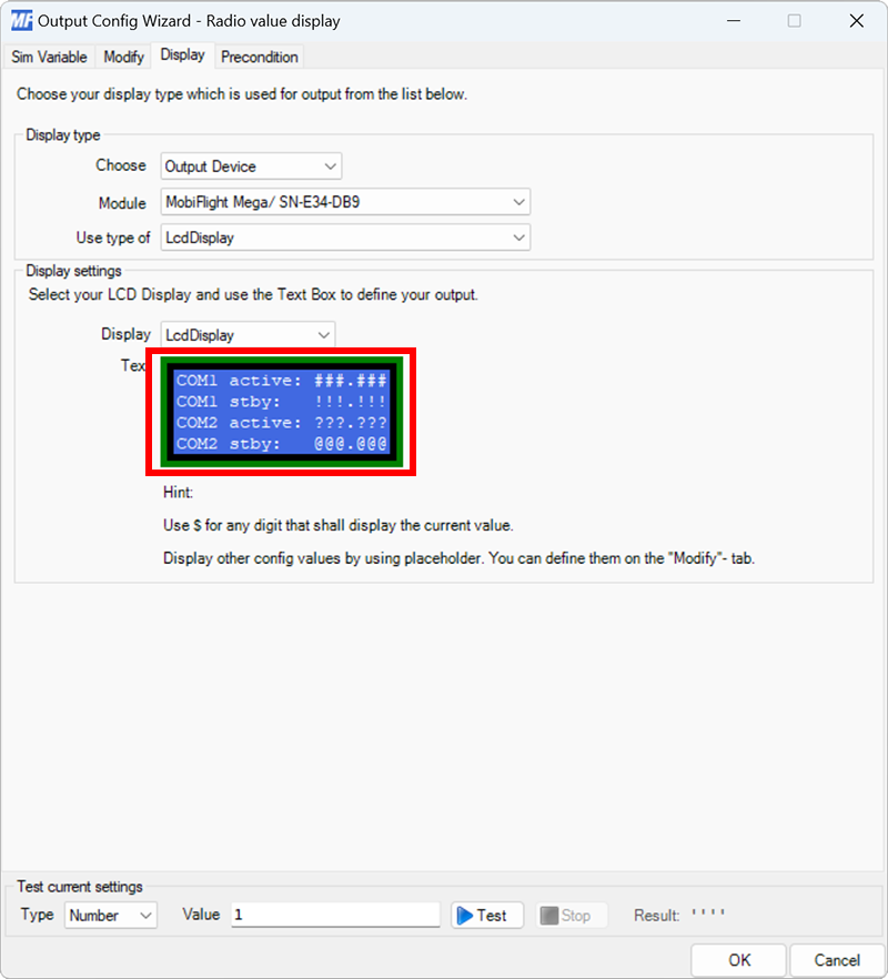
Format the display output
Replace the Text section sample text with the values to show on the display. Use the placeholder symbols from step four to indicate where the digits should be placed, and include a decimal at the appropriate location.
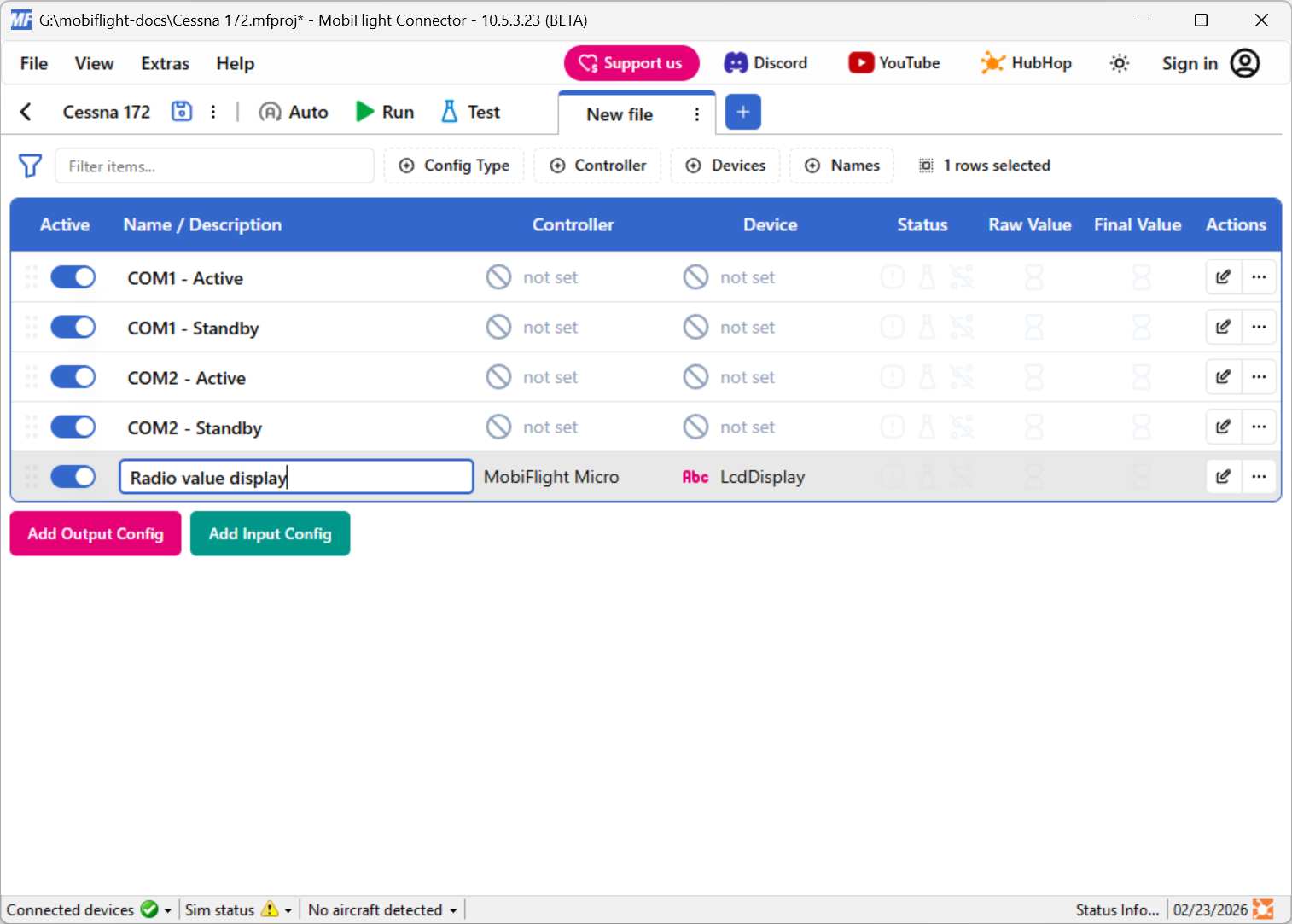
Close the dialog and name the config
Click the OK button to close the dialog, then double-click on the New Output Config name in the main window. Type in a meaningful name for the new config, for example Radio value display, and press enter to apply the change.
Try out the event
Launch Microsoft Flight Simulator. Make sure the MobiFlight Run button is clicked in the toolbar, then verify the display shows the four frequencies.